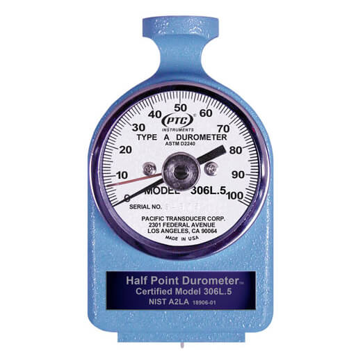
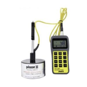
This series of PTC durometer ASTM is designed to measure ASTM hardness of different types. Legendary precision, ease of use and robust, reliable build.
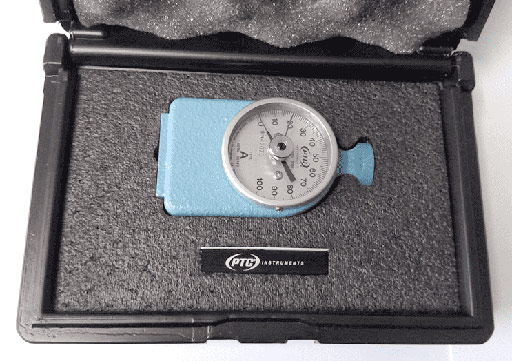
The Model 306L Type A PTC Durometer ASTM is designed to measure ASTM (American Society for Testing and Materials) D2240 Type A hardness. This includes materials such as rubber, elastomers, and other rubber-like materials including neoprene, silicone, santoprene, vinyl, and butyl. Soft plastics, felt, leather, and similar materials generally fall into this same range. PTC® s Model 306L meets or exceeds current ASTM D2240 Specifications. The instrument has a low glare aluminum dial with bold, easy-to-read numbers. The durometer comes standard with a Max Hold hand which retains the peak reading. A top knob with 8-32 threads permits both easy handheld use and attachment to test stands or the accessory Model 441 1kg Constant Load Deadweight. The Model 441 will allow even more consistent measurements when taking readings. Each instrument is individually calibrated. A test block and a sturdy carrying case are included with the durometer.
Features – PTC durometer ASTM
- Max Hold Pointer Standard
- Easy to Read 0 to 100 Point Dial
- Accessory Test Stands Available
- NIST/A2LA to ISO 17025 Certification Available
- Includes Precision Aluminum Test Block
- Carrying Case
- 1kg Constant Load Weight Available (Model 441) (SHORE B 306BL, SHORE A 306L.5, SHORE A 306L)
- Threaded mounting knob permits permanent test stand emplacement (SHORE A 306L)
Specifications
| Scale | SHORE A | SHORE A HALF POINT | SHORE B | SHORE C | SHORE D |
| Model | 306L | 306L.5 | 306BL | 307CL | 307L |
| Range | 0-100 points | 0-100 points | 0-100 points | ||
| Accuracy of | ±1 Point | ±1/2 Point | ±1 Point | ±1 Point | ±1 Point |
| Height | 4 in. (10.2 cm) | 4 in. (10.2 cm) | 4 in. (10.2 cm) | 4 in. (10.2 cm) | 4 in. (10.2 cm) |
| Width | 2-1/4 in. (5.7 cm) | 2-1/4 in. (5.7 cm) | 2-1/4 in. (5.7 cm) | 2-1/4 in. (5.7 cm) | 2-1/4 in. (5.7 cm) |
| Depth | 1-3/4 in. (4.4 cm) | 1-3/4 in. (4.4 cm) | 1-3/4 in. (4.4 cm) | 1-3/4 in. (4.4 cm) | 1-3/4 in. (4.4 cm) |
| Weight | 8 oz. (227 g) | 8 oz. (227 g) | 8 oz. (227 g) | 8 oz. (227 g) | 8 oz. (227 g) |
| Shipping weight | 3lb (1.4kg) | 3lb (1.4kg) | 3lb (1.4kg) | 3lb (1.4kg) | 3lb (1.4kg) |
QUICK TIP:
How to Use a Type A Durometer
OPERATING INSTRUCTIONS
The following procedures are based on ASTM Standard D2240. This standard is recognized as being definitive, however, not all applications require such stringent controls. Readings below 10/A may be inexact and should not be reported for some materials. Readings above 90/A should be made on a Type D durometer.
The surface of the sample to be tested shall be clean and smooth. The sample should be at least 1/4” (6 mm) in thickness unless it is known that identical results are obtained with a thinner specimen. Thinner materials can be stacked to obtain the minimum thickness (DO NOT GLUE). Such results may not agree with those of a solid specimen. The sample should be large enough so that the indenter is at least 1/2” (12 mm) from any edge unless it is known that identical results are obtained when measurements are made closer to the edge. The surface of the specimen shall be flat over a sufficient area to permit the presser foot to contact the specimen over an area having a radius of at least 1/4” from the indenter point. The temperature of the specimen should be 73.4°F ±3.5°F (23°C ±2°C). The specimen should be allowed to rest at this temperature for at least 1 hour prior to testing, as the properties of most materials change with temperature.
Place the specimen on a hard, horizontal surface. Set the ancillary hand of the durometer below 5 points on the dial. Hold the durometer vertically with the point of the indenter at least 1/2 “ from any edge. Apply the presser foot to the specimen as rapidly as possible, without shock, keeping the foot parallel to the surface of the specimen. Apply just sufficient force to obtain firm contact between the presser foot and the specimen. Hold for 1 or 2 seconds, the maximum reading can be obtained from the ancillary hand. If other than a maximum reading is needed, hold the durometer in place without motion and obtain the reading after the required time interval. Make 5 tests at least 1/4” apart and use the average value.
CALIBRATION CHECK
For a complete calibration check of mainspring, and visual and mechanical check of the indenter, the instrument should be returned to PTC® (see Guarantee & Calibration Service) or refer to ASTM D2240 Specifications. PTC® recommends the unit be returned at least every 12 months for this check. For a quick field check, follow the guideline below. Under no circumstance should a test block be used as a standard to calibrate a durometer.
1. The pointer should read zero when no force is applied to the indenter of the durometer.
2. Hand hold the durometer and insert the indenter into the hole of the calibrated test block. Apply enough force to make firm contact between the top surface of the test block and the base of the durometer. The dial reading should agree with the value stamped on the check block (±1). Several tests should be made and the results averaged.
3. The indenter must protrude 0.098 to 0.100 inches below the base of the durometer.
4. When the indenter is fully displaced, the durometer should read 100 points. Use care as to not damage the tip of the indenter.


