
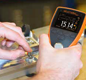
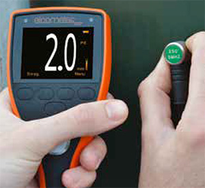
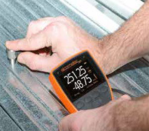
The ultrasonic thickness gauge MTG8 is ideal for measuring and recording material thickness from just 0.2mm (0.008″) to 500mm (20″). With a scratch and solvent resistant display, sealed, heavy duty and impact resistant design – dust and waterproof equivalent to IP54 – the MTG and PTG range is suitable for use in the harshest of environments.
Designed specifically to make them easy to use, calibrate, take readings and create inspection reports. Excellent on smooth, rough and curved, coated or uncoated surfaces. Scratch and solvent-resistant display, sealed, heavy duty and impact resistant design – dust and waterproof equivalent to IP54.
Features
- Easy to use menu structure in multiple languages
- Tough, impact, waterproof and dust resistant equivalent to IP54
- Bright colour screen with permanent backlight
- Stability indicator – a visual indication of both the strength / reliability of ultrasonic signal.
- Ambient light sensor, with adjustable brightness
- Scratch and solvent resistant display; 2.4″ (6cm) TFT
- Large positive feedback buttons
- USB power supply via PC
- Gauge software updates via ElcoMaster® Software(Internet connection required)
- 2 year gauge warranty
MTG / PTG families – distinct features:
MTG & PTG ultrasonic thickness gauges are easy to use, calibrate, take readings and create inspection reports.
MTG & PTG have a measurement accuracy of up to ±1% across their full range. The stability indicator provides a visual indication of both the strength and reliability of the ultrasonic signal.
MTG2 and MTG4 have a set measurement repetition rate of 4Hz (4 readings per second), while MTG6, PTG6, MTG8 & PTG8 have user-selectable measurement rates of 4, 8 and 16 Hz (4, 8 or 16 readings per second).
MTG6, MTG8 & PTG8 have data-logging functionality. MTG6 can store up to 1,500 readings in a single batch while MTG8 & PTG8 store up to 100,000 readings in up to 1,000 sequential or grid type batches, with alpha-numeric batch naming. Compatible with ElcoMaster® and ElcoMaster® Mobile App, downloaded via USB or Bluetooth® direct to PC, iOS* or Android™ mobile.
Is MTG8 right for my project?
| Model Number | MTG8 | |||
| Part Number (with transducer)1 | MTG8BDL-TXC | |||
| Part Number (gauge only) | MTG8BDL | |||
| Limits: 40 definable audible & visual pass/fail warnings | ■ | |||
| Measurement Rate | 4, 8, 16Hz2 | |||
| Measurement Mode | Range3 | Accuracy4 | ||
| Pulsed Echo (P-E) | 0.63-500mm (0.025-20”) | ±0.05mm (0.63-9.99mm) ±0.5% (10.00-500.00mm) |
±0.004” (0.025-0.393”) ±0.5% (0.394-20.00”) |
■ |
| Echo Echo ThruPaint (E-E) | 2.54-20.00mm (0.100-0.787”) |
±0.05mm (2.54-9.99mm) ±0.5% (10.00-20.00mm) |
±0.004” (0.100-0.393”) ±0.5% (0.394-0.787”) |
■ |
| Velocity Mode (VM) | 1,250-10,000m/s (0.0492-0.3937in/µs) | ■ | ||
| Measurement Units | ||||
| mm or inches | ■ | |||
| m/s, inch/µs | ■ | |||
| Repeatability / Stability Indicator | ■ | |||
| Display Mode | ||||
| Reading | ■ | |||
| Selected statistics | ■ | |||
| Scan thickness bar graph | ■ | |||
| Run Chart | ■ | |||
| Readings and Differential | ■ | |||
| B-Scan cross sectional display | ■ | |||
| Selectable Reading Resolution | ||||
| Lo; 0.1mm, 0.01 Inch, 10m/s, or 0.001 in/μs | ■ | |||
| Hi; 0.01mm, 0.001 Inch, 1m/s, or 0.0001 in/μs | ■ | |||
| Statistics | ||||
| Number of readings,n; Mean average, x¯ ; Standard deviation, σ. |
■ | |||
| Lowest reading, Lo; Highest reading, Hi | ■ | |||
| Low / high limit value | ■ | |||
| Reading Range Value | ■ | |||
| Nominal Value | ■ | |||
| Number of readings below low limit | ■ | |||
| Number of readings above high limit | ■ | |||
| Calibration Options | ||||
| Zero (using the integral zero disc) | ■ | |||
| 1 – point | ■ | |||
| 2 – point | ■ | |||
| Material selection; 39 preset materials | ■ | |||
| Factory; resets to the factory calibration | ■ | |||
| Velocity (speed of sound) | ■ | |||
| Known thickness value | ■ | |||
| Calibration Features | ||||
| Calibration lock; with optional PIN Lock | ■ | |||
| Test calibration feature | ■ | |||
| Calibration memories: 3 programmable memories | ■ | |||
| Measurement outside calibration warning | ■ | |||
| Data Logging | ||||
| Number of readings | 100,000 | |||
| Number of batches | 1,000 | |||
| Sequential batching | ■ | |||
| Grid batching | ■ | |||
| Fixed batch size mode; with batch linking | ■ | |||
| Obstruct entry; add ‘obst’ into grid location | ■ | |||
| Delete last reading | ■ | |||
| Date & time stamp | ■ | |||
| Review, clear & delete batches | ■ | |||
| Alpha numeric batch names; user definable | ■ | |||
| Batch review graph | ■ | |||
| Data Output | ||||
| USB to PC | ■ | |||
| Bluetooth® to PC, Android™ & iOS devices | ■ | |||
| ElcoMaster® software | ■ | |||
| Transducer Probe Type | ||||
| Dual Element | ■ | |||
| Auto Transducer Recognition | ■ | |||
| Auto V-path Correction | ■ | |||
| Battery Type5 | 2 x AA | |||
| Battery Life5Alkaline: 15 hours Lithium: 28 hours | ■ | |||
| Operating Temperature -10 to 50° (14 to 122°F) | ■ | |||
| Size (w x h x d) 145 x 73 x 37mm (5.7 x 2.84 x 1.46″) | ■ | |||
| Gauge Weight (including batteries) | 210g (7.4oz) | |||
Measurement modes explained
The Elcometer NDT MTG & PTG range has a number of measurement modes available to help the user establish the most accurate thickness value. The modes available vary between models but normally increase as the model number increases.
| Pulsed – Echo Mode (P-E) | Ideal for pit and flaw detection, the total thickness from the base of the transducer to the material density boundary (typically the back wall) is measured. |
| Echo – Echo Mode (E-E) | Ideal for measuring thinner materials between 0.15-10.15mm (0.006 – 0.4″) thick, Echo-Echo mode measures from the top surface to the material density boundary ( typically the back wall). |
| Echo – Echo ThruPaint™ Mode (E-E) | Sometimes known as ThruPaint™ mode, the coating thickness is ignored and the material thickness from the top surface of the material to the material density boundary (typically the back wall) is measured. To use Echo-Echo ThruPaint™ mode, a high damped, coating thickness transducer is required |
| Interface Echo (I-E) | A highly accurate measurement mode, Interface Echo displays the total thickness from the top surface to the material density boundary |
| Plastic Mode (PLAS) | A mode specifically used for measuring very thin plastics. A special graphite delay line accessory is required for this mode. |
| Velocity Mode (VM) | Velocity mode measures the speed of sound of materials and is ideal for determining the homogeneity of a material/alloy and the correct velocity of a material for calibration. |
Displays explained
The Elcometer NDT MTG & PTG range has a choice of measurement modes allowing the user to select the most appropriate for their application. The modes available vary between models but normally increase as the model number increases.
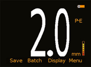 |
The Display | All gauges have a fully customisable, scratch and solvent resistant colour LCD display. Measurement modes available include Pulsed-Echo (P-E), Echo-Echo ThruPaint™ (E-E),Interface Echo (I-E),Plastic Mode (PLAS) and Velocity mode (VM) (for more information on measurement modes, see page 3). A choice of measurement units are available, depending on the measurement mode selected. A stability indicator shows clearly both the strength and reliability of the ultrasonic signal. |
 |
Scan Mode | When enabled, users can slide the transducer over a large surface area whilst the gauge takes readings at a rate of 16 Hz (16 readings per second). During each scan, the live thickness is displayed together with an analogue bar graph showing the thickness relative to the set nominal value and any user defined limits, with audible and visual warnings if any readings fall outside the set limits. When the transducer is lifted off the surface, the average, lowest and highest thickness value is displayed making scan mode ideal for checking a sample’s overall uniformity. |
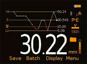 |
Run Chart | A trend graph of the last 20 readings, showing the variation in material thickness over the test area. The graph is updated automatically as each reading is taken and any readings outside the set and enabled limits are displayed in red thus allowing the user to easily identify areas where corrosion may be present or the material is too thick for purpose. |
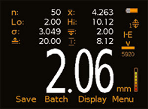 |
On Screen Statistics | Up to 8 statistical values can be displayed from a choice of number of readings (n) , lowest, highest and average reading (Lo, Hi, x),standard deviation (σ),low and high limit values, nominal value and range. |
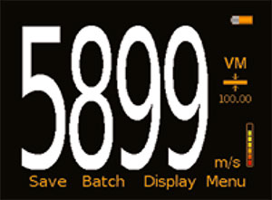 |
Velocity Mode | Velocity mode measures the speed of sound of materials and is ideal for determining the homogeneity of a material/alloy and the correct velocity of a material for calibration. |
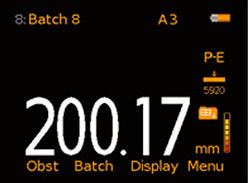 |
Sequential or Grid Batching | Individual readings can be stored in up to 1,000 sequential or grid type,alpha-numeric batches, together with date and time stamp and reading location*. Users have the option to view batch readings, statistics and a graph of all readings stored within the batch. The obstruction feature (Obst)*,allows the user to record areas where measurements could not be taken. |
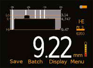 |
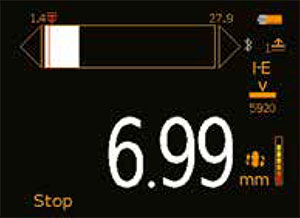
B-Scan Reading | A time based, cross sectional 2 dimensional B-Scan provides a graphical view of the material under test, ideal for relative depth analysis. The zoom of the B-Scan reading can either be set to automatic or can be defined by the user to focus on areas of interest. |
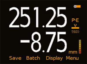 |
Differential Mode | Once a user defined nominal thickness value has been set, the gauge displays the measured thickness together with the variation from the set nominal value thus indicating areas of the material which are thinner or thicker than expected. |
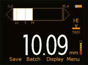 |
Bar Graph | An analogue representation of the current measurement value together with the highest (Hi),lowest (Lo) and average (x) reading. The graph is updated automatically when each reading is taken. |
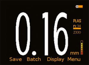 |
Plastic Mode | Plastic mode is specifically designed for measuring very thin plastics. |

The ultrasonic thickness gauge MTG8 is ideal for measuring and recording material thickness from just 0.2mm (0.008″) to 500mm (20″). With a scratch and solvent resistant display, sealed, heavy duty and impact resistant design – dust and waterproof equivalent to IP54 – the MTG and PTG range is suitable for use in the harshest of environments.
Designed specifically to make them easy to use, calibrate, take readings and create inspection reports. Excellent on smooth, rough and curved, coated or uncoated surfaces. Scratch and solvent-resistant display, sealed, heavy duty and impact resistant design – dust and waterproof equivalent to IP54.
Features
- Easy to use menu structure in multiple languages
- Tough, impact, waterproof and dust resistant equivalent to IP54
- Bright colour screen with permanent backlight
- Stability indicator – a visual indication of both the strength / reliability of ultrasonic signal.
- Ambient light sensor, with adjustable brightness
- Scratch and solvent resistant display; 2.4″ (6cm) TFT
- Large positive feedback buttons
- USB power supply via PC
- Gauge software updates via ElcoMaster® Software(Internet connection required)
- 2 year gauge warranty
MTG / PTG families – distinct features:
MTG & PTG ultrasonic thickness gauges are easy to use, calibrate, take readings and create inspection reports.
MTG & PTG have a measurement accuracy of up to ±1% across their full range. The stability indicator provides a visual indication of both the strength and reliability of the ultrasonic signal.
MTG2 and MTG4 have a set measurement repetition rate of 4Hz (4 readings per second), while MTG6, PTG6, MTG8 & PTG8 have user-selectable measurement rates of 4, 8 and 16 Hz (4, 8 or 16 readings per second).
MTG6, MTG8 & PTG8 have data-logging functionality. MTG6 can store up to 1,500 readings in a single batch while MTG8 & PTG8 store up to 100,000 readings in up to 1,000 sequential or grid type batches, with alpha-numeric batch naming. Compatible with ElcoMaster® and ElcoMaster® Mobile App, downloaded via USB or Bluetooth® direct to PC, iOS* or Android™ mobile.
Is MTG8 right for my project?
| Model Number | MTG8 | |||
| Part Number (with transducer)1 | MTG8BDL-TXC | |||
| Part Number (gauge only) | MTG8BDL | |||
| Limits: 40 definable audible & visual pass/fail warnings | ■ | |||
| Measurement Rate | 4, 8, 16Hz2 | |||
| Measurement Mode | Range3 | Accuracy4 | ||
| Pulsed Echo (P-E) | 0.63-500mm (0.025-20”) | ±0.05mm (0.63-9.99mm) ±0.5% (10.00-500.00mm) |
±0.004” (0.025-0.393”) ±0.5% (0.394-20.00”) |
■ |
| Echo Echo ThruPaint (E-E) | 2.54-20.00mm (0.100-0.787”) |
±0.05mm (2.54-9.99mm) ±0.5% (10.00-20.00mm) |
±0.004” (0.100-0.393”) ±0.5% (0.394-0.787”) |
■ |
| Velocity Mode (VM) | 1,250-10,000m/s (0.0492-0.3937in/µs) | ■ | ||
| Measurement Units | ||||
| mm or inches | ■ | |||
| m/s, inch/µs | ■ | |||
| Repeatability / Stability Indicator | ■ | |||
| Display Mode | ||||
| Reading | ■ | |||
| Selected statistics | ■ | |||
| Scan thickness bar graph | ■ | |||
| Run Chart | ■ | |||
| Readings and Differential | ■ | |||
| B-Scan cross sectional display | ■ | |||
| Selectable Reading Resolution | ||||
| Lo; 0.1mm, 0.01 Inch, 10m/s, or 0.001 in/μs | ■ | |||
| Hi; 0.01mm, 0.001 Inch, 1m/s, or 0.0001 in/μs | ■ | |||
| Statistics | ||||
| Number of readings,n; Mean average, x¯ ; Standard deviation, σ. |
■ | |||
| Lowest reading, Lo; Highest reading, Hi | ■ | |||
| Low / high limit value | ■ | |||
| Reading Range Value | ■ | |||
| Nominal Value | ■ | |||
| Number of readings below low limit | ■ | |||
| Number of readings above high limit | ■ | |||
| Calibration Options | ||||
| Zero (using the integral zero disc) | ■ | |||
| 1 – point | ■ | |||
| 2 – point | ■ | |||
| Material selection; 39 preset materials | ■ | |||
| Factory; resets to the factory calibration | ■ | |||
| Velocity (speed of sound) | ■ | |||
| Known thickness value | ■ | |||
| Calibration Features | ||||
| Calibration lock; with optional PIN Lock | ■ | |||
| Test calibration feature | ■ | |||
| Calibration memories: 3 programmable memories | ■ | |||
| Measurement outside calibration warning | ■ | |||
| Data Logging | ||||
| Number of readings | 100,000 | |||
| Number of batches | 1,000 | |||
| Sequential batching | ■ | |||
| Grid batching | ■ | |||
| Fixed batch size mode; with batch linking | ■ | |||
| Obstruct entry; add ‘obst’ into grid location | ■ | |||
| Delete last reading | ■ | |||
| Date & time stamp | ■ | |||
| Review, clear & delete batches | ■ | |||
| Alpha numeric batch names; user definable | ■ | |||
| Batch review graph | ■ | |||
| Data Output | ||||
| USB to PC | ■ | |||
| Bluetooth® to PC, Android™ & iOS devices | ■ | |||
| ElcoMaster® software | ■ | |||
| Transducer Probe Type | ||||
| Dual Element | ■ | |||
| Auto Transducer Recognition | ■ | |||
| Auto V-path Correction | ■ | |||
| Battery Type5 | 2 x AA | |||
| Battery Life5Alkaline: 15 hours Lithium: 28 hours | ■ | |||
| Operating Temperature -10 to 50° (14 to 122°F) | ■ | |||
| Size (w x h x d) 145 x 73 x 37mm (5.7 x 2.84 x 1.46″) | ■ | |||
| Gauge Weight (including batteries) | 210g (7.4oz) | |||
Measurement modes explained
The Elcometer NDT MTG & PTG range has a number of measurement modes available to help the user establish the most accurate thickness value. The modes available vary between models but normally increase as the model number increases.
| Pulsed – Echo Mode (P-E) | Ideal for pit and flaw detection, the total thickness from the base of the transducer to the material density boundary (typically the back wall) is measured. |
| Echo – Echo Mode (E-E) | Ideal for measuring thinner materials between 0.15-10.15mm (0.006 – 0.4″) thick, Echo-Echo mode measures from the top surface to the material density boundary ( typically the back wall). |
| Echo – Echo ThruPaint™ Mode (E-E) | Sometimes known as ThruPaint™ mode, the coating thickness is ignored and the material thickness from the top surface of the material to the material density boundary (typically the back wall) is measured. To use Echo-Echo ThruPaint™ mode, a high damped, coating thickness transducer is required |
| Interface Echo (I-E) | A highly accurate measurement mode, Interface Echo displays the total thickness from the top surface to the material density boundary |
| Plastic Mode (PLAS) | A mode specifically used for measuring very thin plastics. A special graphite delay line accessory is required for this mode. |
| Velocity Mode (VM) | Velocity mode measures the speed of sound of materials and is ideal for determining the homogeneity of a material/alloy and the correct velocity of a material for calibration. |
Displays explained
The Elcometer NDT MTG & PTG range has a choice of measurement modes allowing the user to select the most appropriate for their application. The modes available vary between models but normally increase as the model number increases.
|
The Display | All gauges have a fully customisable, scratch and solvent resistant colour LCD display. Measurement modes available include Pulsed-Echo (P-E), Echo-Echo ThruPaint™ (E-E),Interface Echo (I-E),Plastic Mode (PLAS) and Velocity mode (VM) (for more information on measurement modes, see page 3). A choice of measurement units are available, depending on the measurement mode selected. A stability indicator shows clearly both the strength and reliability of the ultrasonic signal. |
|
Scan Mode | When enabled, users can slide the transducer over a large surface area whilst the gauge takes readings at a rate of 16 Hz (16 readings per second). During each scan, the live thickness is displayed together with an analogue bar graph showing the thickness relative to the set nominal value and any user defined limits, with audible and visual warnings if any readings fall outside the set limits. When the transducer is lifted off the surface, the average, lowest and highest thickness value is displayed making scan mode ideal for checking a sample’s overall uniformity. |
|
Run Chart | A trend graph of the last 20 readings, showing the variation in material thickness over the test area. The graph is updated automatically as each reading is taken and any readings outside the set and enabled limits are displayed in red thus allowing the user to easily identify areas where corrosion may be present or the material is too thick for purpose. |
|
On Screen Statistics | Up to 8 statistical values can be displayed from a choice of number of readings (n) , lowest, highest and average reading (Lo, Hi, x),standard deviation (σ),low and high limit values, nominal value and range. |
|
Velocity Mode | Velocity mode measures the speed of sound of materials and is ideal for determining the homogeneity of a material/alloy and the correct velocity of a material for calibration. |
|
Sequential or Grid Batching | Individual readings can be stored in up to 1,000 sequential or grid type,alpha-numeric batches, together with date and time stamp and reading location*. Users have the option to view batch readings, statistics and a graph of all readings stored within the batch. The obstruction feature (Obst)*,allows the user to record areas where measurements could not be taken. |
|
B-Scan Reading | A time based, cross sectional 2 dimensional B-Scan provides a graphical view of the material under test, ideal for relative depth analysis. The zoom of the B-Scan reading can either be set to automatic or can be defined by the user to focus on areas of interest. |
|
Differential Mode | Once a user defined nominal thickness value has been set, the gauge displays the measured thickness together with the variation from the set nominal value thus indicating areas of the material which are thinner or thicker than expected. |
|
Bar Graph | An analogue representation of the current measurement value together with the highest (Hi),lowest (Lo) and average (x) reading. The graph is updated automatically when each reading is taken. |
|
Plastic Mode | Plastic mode is specifically designed for measuring very thin plastics. |