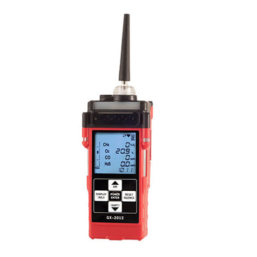
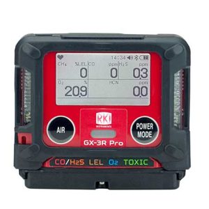
Compact, feature-rich Gas Tracer is RKI’s smallest personal 4 sensor monitor with a built-in sample pump
Weighing only 12.3 ounces, it has many features which set the Gas Tracer apart from the competition. For example, it can monitor the standard gas safety hazards for gas/pipeline operations, (LEL combustibles, Oxygen content, and Carbon Monoxide), and it also has a high-sensitivity ppm CH4 leak tracker mode which reads down to 10 ppm. It can also measure 100% volume Methane and dynamically display either % LEL, or % volume with its auto-ranging ability. The Gas Tracer is excellent for gas line purge testing and detection of small gas leaks.
**Gas Tracer, 4 sensors, PPM CH4 / LEL / % volume CH4 / O2 base, with Li-Ion battery pack only with 100-240 VAC charger (Alkaline battery pack not included)**
Gas Tracer introduction
The Gas Tracer’s large LCD display shows all gas readings, battery level, current time, and will automatically backlight in alarm conditions. Other standard mode alarm types include vibration, visual, and audible alarms that can be set to latching or non-latching. Controlled by a microprocessor, the Gas Tracer continuously checks itself for sensor connections, low battery, circuit trouble, low flow, and calibration errors. The Gas Tracer can operate on either a Li-Ion battery pack or an alkaline battery pack. The batteries are simple to replace requiring no tools to access the removable battery compartment or pack.
Calibration and bump test intervals and reminders are user adjustable and can be set to either go into alarm or to lock the user out of normal measurement mode once a calibration period has expired. Calibrations can be performed
automatically or individually in a single calibration mode. The Gas Tracer is also compatible with the economical SDM-2012 single channel calibration station.
Specifications
| Gas Detected |
Combustible Gases
(Methane as standard) |
% Volume
Methane |
PPM
Methane |
Oxygen (O2)
|
Carbon Monoxide (CO)
|
| Detection Principle |
Catalytic combustion
|
Thermal conductivity
|
MOS
catalytic |
Galvanic cell
|
Electrochemical cell
|
| Detection Range |
0 ~ 100% LEL
|
0 ~ 100% Vol.
|
0 ~ 5000 ppm
optional 10,000 ppm range version available |
0 ~ 40% Vol.
|
0 ~ 500 ppm
|
| Accuracy Statement (whichever is greater) |
± 5% of reading or
± 2% LEL |
± 5% of reading or ± 2% of full scale
|
± 10% of reading or ± 50 ppm CH4
|
± 0.5% O2
|
± 5% of reading or ± 5 ppm CO
|
| Sampling Method | Internal sample pump, flow rate nominal 0.5 LPM, includes a hydrophobic filter | ||||
| Display | Digital LCD with 7 segments, auto backlight during alarm | ||||
| Preset Alarms (User Adjustable) |
1st alarm 10% LEL 2nd alarm 50% LEL Over alarm 100% LEL |
No alarms for % Vol. CH4 |
Increasing tone/light pulse as concentration increases | Low alarm 19.5% High alarm 23.5% Over alarm 40.0% | 1st 25 ppm 2nd 50 ppm TWA 25 ppm STEL 200 ppm Over 500 ppm |
| Alarms Types | Leak Tracker Mode: Escalating audible/visual alarm, changes with gas level (audible can be turned off) Gas alarms: 1st and 2nd, STEL, TWA (user adjustable) and OVER Trouble alarms: Sensor connection, low battery, low flow, circuit trouble and calibration error |
||||
| Alarm Methods | Gas alarms: Flashing lights, two-tone buzzer, and vibration Trouble alarms: Flashing lights, trouble displayed, intermittent buzzer, and vibration |
||||
| Operating Temp. & Humidity | -20°C to +50°C (-4°F to +122°F) 0 to 95% RH, non-condensing |
||||
| Response Time | Within 30 seconds (T90) | ||||
| Continuous Operation | Alkaline battery: 15 hours Li-Ion battery: 10 hours 70°F (21°C) |
||||
| Power Source | Li-Ion battery pack, or 3 “AA” Alkaline battery pack; interchangeable | ||||
| Safety Rating | ATEX, TIIS, IECEx, CE, or optionally: c CSA us classified, as intrinsically safe. Class I, Division 1, Groups A, B, C, D Note: Either ATEX (USA and worldwide) or CSA (Canada) version must be specified when ordering. |
||||
| Dimension & Weight | Approx. 143 (H) x 71 (W) x 43 (D) mm (5.6” H x 2.8” W x 1.6” D),approx. 350 g (12.3 ounces) | ||||
| Case Material | High dust & water-resistant design. RFI shielded high impact plastic with protective rubber over-molding | ||||
| Controls | Five buttons: POWER / ENTER, DISPLAY, AIR, RESET, SHIFT | ||||
| Standard Accessories | • Belt clip • Rubber nozzle, 2.5” • Datalogging software • 10” Probe • Manual • Quick reference card • 10’ Hose • Training CD |
||||
| Optional Accessories | • SDM-2012 calibration stations • Calibration kit • Li-Ion battery pack • AC or DC Charger • Sample draw hoses (10’ standard, up to 50’ max. available) • Carrying case |
||||
| Configurations | 1, 2, 3, 4, or 5 sensor units Li-Ion or alkaline battery pack options |
||||
RK72029165C / MFR: 72-0291-65-C
QUICK TIP:
Turning On the Gas Tracer, Normal Mode Only
The following description of the Gas Tracer start up sequence assumes that the following items in Maintenance Mode are turned on: LNCH BRK, ID DISP, CL RMNDR, and BP RMNDR. If any of these items is turned off, then the corresponding screen will not appear. This description also assumes that Bar Hole Mode and Leak Check Mode are not active.
1. Connect the tapered rubber nozzle or the sample hose to the Gas Tracer’s quick connect inlet fitting.
2. If a sample hose is used, screw the probe onto the sample hose’s threaded fitting.
3. Press and briefly hold down the POWER ENTER button. Release the button when you hear a beep.
4. If LNCH BRK is turned on, the Resume Datalog Screen displays.
5. If CL RMNDR is turned on (factory setting), the screen that appears next depends on how CL EXPRD is set in the Maintenance Mode Menu (page 146).
6. If BP RMNDR is turned on (factory setting is OFF), the screen that appears next depends on how BP EXPRD is set in the Maintenance Mode Menu (page 146).
7. If ID DISP is turned on (see page 150), the User ID Screen displays for a few seconds and then the Station ID Screen displays for a few seconds
8. The Date/Time Screen appears for a few seconds
9. The Battery Level and Alarm Pattern Screen appears next.
10. The display then indicates the following items for about a second each:
• Full-scale values for all channels
• Warning setpoint (low gas alarm) for all channels
• Alarm setpoint (high gas alarm) for all channels
• STEL alarm setpoint for the CO channel
• TWA alarm setpoint for the CO channel
11. If the Gas Tracer experiences a sensor failure during start-up, a screen indicating which sensor failed displays. In the example below, the CO sensor has failed.
12. The Gas Tracer is now operating in Normal Mode and monitoring for gas in Measuring Mode. The Normal Operation Screen appears.


